
Studio Flash Explained:
Flash Duration
Flash Duration
Flash Duration
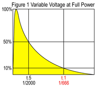
Figure 1 depicts the typical characteristics of a Xenon flashtube. When the tube is fired there is a rapid ionization period as the tube output rises to maximum brightness. This is followed by an exponential decline in tube current, voltage and light as the capacitors are discharged to zero. The standard engineering term for stating flash duration is “t.5”. This describes the time it takes for 50% of the total flashpower to be dissipated. Whenever the simple designation “Flash Duration” is specified it can be assumed to be the t.5 spec.
However, the t.5 spec doesn’t adequately predict the actual motion freezing capability of a flash. There is a much longer trailing edge that continues to emit the remaining 50% of the light. This causes considerably more motion blur than the t.5 spec implies. In order to better compare flash duration specs to an equivalent shutter speed, the term “t.1” was introduced by the photo industry. t.1 specifies the time it takes for 90% of the total flash to be emitted. But even following the t.1 time there is still light being emitted at sufficient intensity to cause some ghosting or motion trails.
Variable Voltage Control of Flashpower
The vast majority of studio monoflash units, regardless of price, control the flashpower by varying the voltage to which the flash capacitors are charged. Variable voltage control is the primary method of flashpower control in our AlienBees™ and White Lightning™ X-Series flash units.
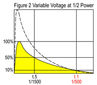
Figure 2 depicts such a flash when the power is reduced to 50%. Notice the discharge curve is similar to the Full Power curve, but that the intensity is reduced and the discharge time is slower. Both the t.1 and t.5 flash durations are longer because of the reduced voltage and flashtube current.
Color Temperature and Variable Voltage
Another result of the reduced voltage and current is a lowering of color temperature that is proportional to the amount of power reduction via voltage variable means.
Summation of Variable Voltage Flash Characteristics
Flash units using variable voltage power control (including the Paul C. Buff™ AlienBees™, White Lightning™ X-Series and Zeus™ flash systems) typically exhibit an increase in flash duration roughly equal to 20% of the full power flash duration being added for each full f-stop in power reduction and about a 75K decrease in color temperature per f-stop of power reduction.
IGBT Control of Flashpower
Essentially all low power camera flashes (speedlites) employ IGBT control of flash power instead of variable voltage control. This technology is easily implemented in low power units, but only recently have IGBT devices become available with sufficient power handling capacity for use in higher powered studio flash, especially those offering fast flash durations.
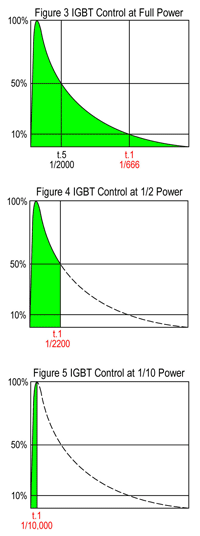
In looking at Figures 3, 4 and 5, it is seen that, in an IGBT flash, the voltage and current remain constant as power is reduced and that power is reduced by abruptly shutting the tube off once the desired amount of light has been emitted. This results in flash durations that become shorter and shorter as power is reduced, as well as the complete elimination of the exponential flash tail that is responsible for motion blur in non-IGBT flash units.
Notice in Figure 2 that a 50% power reduction in a conventional studio flash lengthens the t.1 flash duration from 1/666 second to 1/500 second while the same power reduction in an IGBT flash (Figure 4) shortens the t.1 duration to 1/2200 second and that the trailing edge tail is completely removed.
Figure 5 illustrates the extremely short 1/10,000 second t.1 time when the power is more dramatically reduced.
Color Temperature with IGBT Control
It should be understood that the color temperature of a flashtube is, in part, determined by the voltage and current at which it is operated. In Figures 1 and 3, the color temperature emitted is not constant throughout the discharge period. Rather, the color temperature is higher (more blue) at the beginning of the discharge and becomes lower (more red) as the waveform declines. Thus, it is the average of the beginning and ending color temperatures that form the effective color temperature for the exposure.
Speedlites typically produce higher and higher color temperature as power is reduced because of discarding the lower color temperature “tail” and keeping the higher color temperature initial portion.
The Einstein™ E640 flash unit: When used in its CONSTANT COLOR mode, Einstein™ combines IGBT shutoff of the flashtube with an exacting digital adjustment of the capacitor voltage in order to achieve a constant 5600K +/- 50K color temperature at any power setting (when used with the 5600K flashtube). In ACTION MODE, Einstein™ allows the color temperature to rise slightly as power is reduced as a means of achieving the fastest possible flash durations. Both the t.1 flash duration and the color temperature are displayed on the rear panel LCD in all modes and at all power settings.
Figure 1 depicts the typical characteristics of a Xenon flashtube. When the tube is fired there is a rapid ionization period as the tube output rises to maximum brightness. This is followed by an exponential decline in tube current, voltage and light as the capacitors are discharged to zero. The standard engineering term for stating flash duration is “t.5”. This describes the time it takes for 50% of the total flashpower to be dissipated. Whenever the simple designation “Flash Duration” is specified it can be assumed to be the t.5 spec.
However, the t.5 spec doesn’t adequately predict the actual motion freezing capability of a flash. There is a much longer trailing edge that continues to emit the remaining 50% of the light. This causes considerably more motion blur than the t.5 spec implies. In order to better compare flash duration specs to an equivalent shutter speed, the term “t.1” was introduced by the photo industry. t.1 specifies the time it takes for 90% of the total flash to be emitted. But even following the t.1 time there is still light being emitted at sufficient intensity to cause some ghosting or motion trails.
Variable Voltage Control of Flashpower
The vast majority of studio monoflash units, regardless of price, control the flashpower by varying the voltage to which the flash capacitors are charged. Variable voltage control is the primary method of flashpower control in our AlienBees™ and White Lightning™ X-Series flash units.
Figure 2 depicts such a flash when the power is reduced to 50%. Notice the discharge curve is similar to the Full Power curve, but that the intensity is reduced and the discharge time is slower. Both the t.1 and t.5 flash durations are longer because of the reduced voltage and flashtube current.
Color Temperature and Variable Voltage
Another result of the reduced voltage and current is a lowering of color temperature that is proportional to the amount of power reduction via voltage variable means.
Summation of Variable Voltage Flash Characteristics
Flash units using variable voltage power control (including the Paul C. Buff™ AlienBees™, White Lightning™ X-Series and Zeus™ flash systems) typically exhibit an increase in flash duration roughly equal to 20% of the full power flash duration being added for each full f-stop in power reduction and about a 75K decrease in color temperature per f-stop of power reduction.
IGBT Control of Flashpower
Essentially all low power camera flashes (speedlites) employ IGBT control of flash power instead of variable voltage control. This technology is easily implemented in low power units, but only recently have IGBT devices become available with sufficient power handling capacity for use in higher powered studio flash, especially those offering fast flash durations.
In looking at Figures 3, 4 and 5, it is seen that, in an IGBT flash, the voltage and current remain constant as power is reduced and that power is reduced by abruptly shutting the tube off once the desired amount of light has been emitted. This results in flash durations that become shorter and shorter as power is reduced, as well as the complete elimination of the exponential flash tail that is responsible for motion blur in non-IGBT flash units.
Notice in Figure 2 that a 50% power reduction in a conventional studio flash lengthens the t.1 flash duration from 1/666 second to 1/500 second while the same power reduction in an IGBT flash (Figure 4) shortens the t.1 duration to 1/2200 second and that the trailing edge tail is completely removed.
Figure 5 illustrates the extremely short 1/10,000 second t.1 time when the power is more dramatically reduced.
Color Temperature with IGBT Control
It should be understood that the color temperature of a flashtube is, in part, determined by the voltage and current at which it is operated. In Figures 1 and 3, the color temperature emitted is not constant throughout the discharge period. Rather, the color temperature is higher (more blue) at the beginning of the discharge and becomes lower (more red) as the waveform declines. Thus, it is the average of the beginning and ending color temperatures that form the effective color temperature for the exposure.
Speedlites typically produce higher and higher color temperature as power is reduced because of discarding the lower color temperature “tail” and keeping the higher color temperature initial portion.
The Einstein™ E640 flash unit: When used in its CONSTANT COLOR mode, Einstein™ combines IGBT shutoff of the flashtube with an exacting digital adjustment of the capacitor voltage in order to achieve a constant 5600K +/- 50K color temperature at any power setting (when used with the 5600K flashtube). In ACTION MODE, Einstein™ allows the color temperature to rise slightly as power is reduced as a means of achieving the fastest possible flash durations. Both the t.1 flash duration and the color temperature are displayed on the rear panel LCD in all modes and at all power settings.

© PAUL C. BUFF, INC | About Us | Help Center | Privacy Policy | Site Map | Toll Free 1.800.443.5542 | Local 615.383.3982 | Contact Us